GNSS Signal Measurement Models
Pseudorange measurement Models
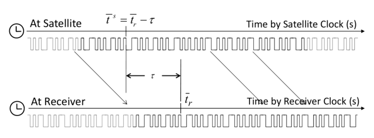
The pseudorange is defined as ʺthe distance from the receiver antenna to the satellite antenna including receiver and satellite clock offsets (and other biases, such as atmospheric delays)ʺ. The \(L_i\) pseudorange \(P_{r,i}^s\) can be expressed by using the signal reception time \(\bar t_r\) (s) measured by the receiver clock and the signal transmission time \(\bar t^s\) (s) measured by the satellite clock as:
The equation can be written by using the geometric range \(\rho_r^s\) between satellite and receiver antennas, the receiver and satellite clock biases \(dt_r dT^s\), the ionospheric and tropospheric delay \(I_{r,i}^s\), \(T_r^s\), and the measurement error \(\varepsilon_p\) as:
Carrier‐phase and phase‐range measurement model
The carrier‐phase is ʺ… actually being a measurement on the beat frequency between the received carrier of the satellite signal and a receiver‐generated reference frequencyʺ. The \(L_i\) carrier‐phase \(\phi_{r,i}^s\) can be expressed as:
where \(t_0\) is the initial time (s), \(\phi_{r,i}(t)\) is the \(L_i\) phase (cycle) of receiver local oscillator and \(\phi_i^s(t)\) is the \(L_i\) phase (cycle) of transmitted navigation signal at the time \(t\). \(\phi_{r,0,i}\) is the \(L_i\) initial phase (cycle) of receiver local oscillator and \(\phi_{r,0,i}^s\) is the \(L_i\) initial phase (cycle) of transmitted navigation signal at the time \(t_0\).
The \(L_i\) phase‐range \(\Phi_{r,i}^s\), defined as the carrier‐phase multiplied by the carrier frequency \(\lambda_i\) in m, also can be expressed by using the carrier phase bias \(B_{r,i}^s\), and carrier‐phase correction terms \(d\Phi_{r,i}^s\), including antenna phase center offsets and variations, station displacement by earth tides, phase windup effect and relativity correction on the satellite clock as:
where:
\[\begin{split}&B_{r,i}^s=\phi_{0,i}^s+N_{r,i}^s\\ &d\Phi_{r,i}^s=-{\pmb{d}_{r,pco,i}}^Te_{r,enu}^s+{(\pmb{E}^s\pmb{d}_{pco,i}^s)}^T& \pmb{e}_r^s+d_{r,pcv,i}(El)+d_{pcv,i}^s(\theta)-{\pmb{d}_{r,disp}}^T\pmb{e}_{r,enu}^s+\lambda_i\phi_{pw}\end{split}\]
\(N_{r,i}^s\) is often called as carrier‐phase integer ambiguity, carrier‐cycle ambiguity or simply ambiguity. For the detailed formulation of the carrier‐phase correction terms.