EVK Vehicle Installation
Reference coordinate frames
In order to install the OpenRTK330 EVB on vehicle for driving test, a few reference frames listed below has to be defined
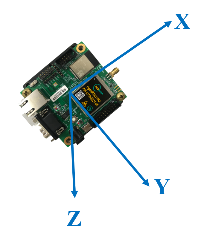
- The IMU body frame is defined as below and shown in the figure. By default the INS solution of OpenRTK330 is provided at the center of navigation of the IMU (refer to the mechanical drawing for accurate IMU navigation center position on the EVB).
x-axis: points to the same direction as the SMA antenna interface
z-axis: perpendicular to x-axis and points downward
y-axis: points to the side of the EVK and completes a right-handed coordinate system
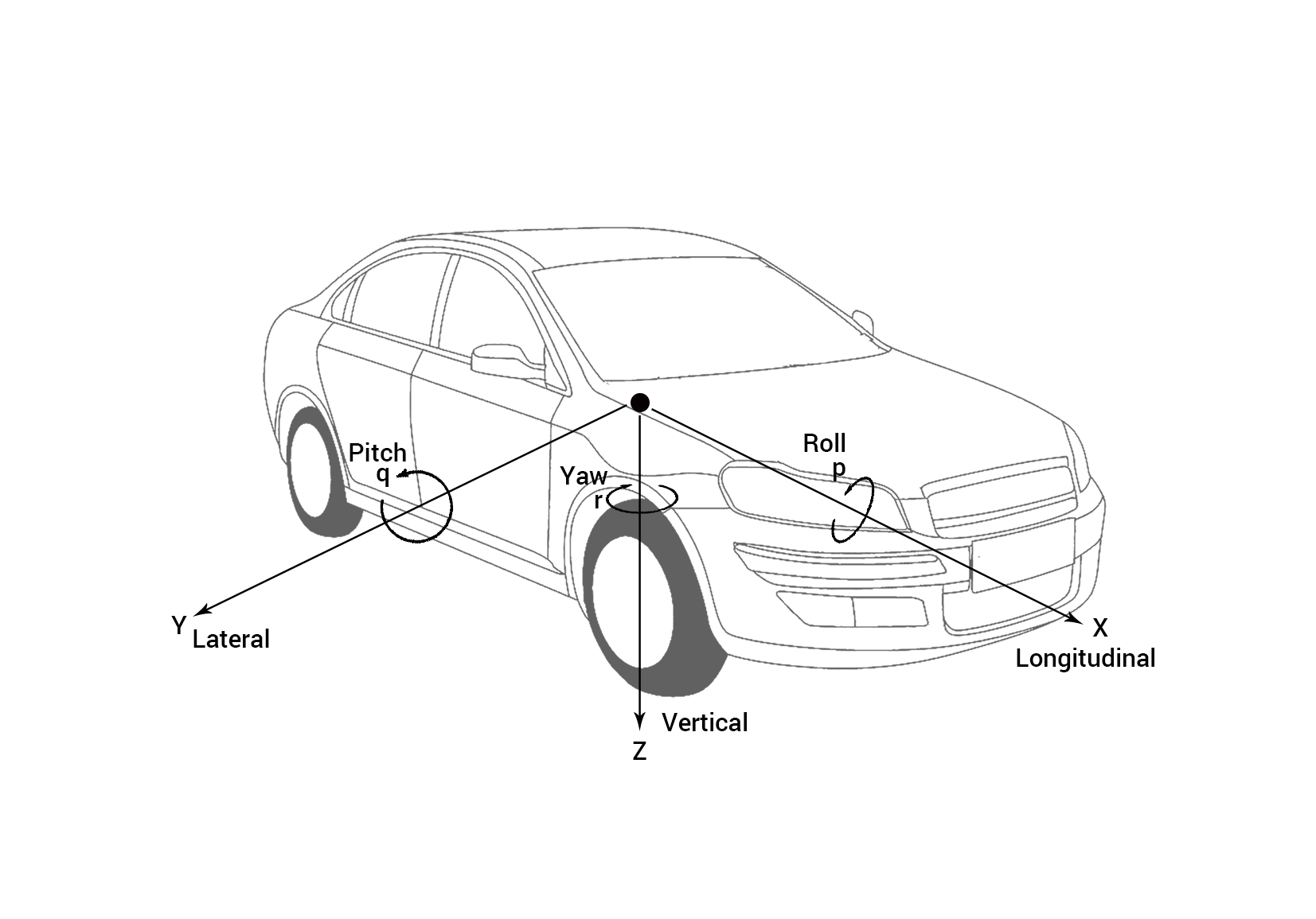
The vehicle frame is defined as
x-axis: points out the front of the vehicle in the driving direction
z-axis: points down to the ground
y-axis: completes the right-handed system
The local level navigation frame is defined as
- x-axis: points north
- z-axis: points down parallel with local gravity
- y-axis: points east
The user output frame is used to transfer the INS solution to a user designated position.
Installation Parameters
Depends on the vehicle installation of the OpenRTK330 system, user has to configure two types of offsets to make the GNSS integrated INS solution work
Translation offset
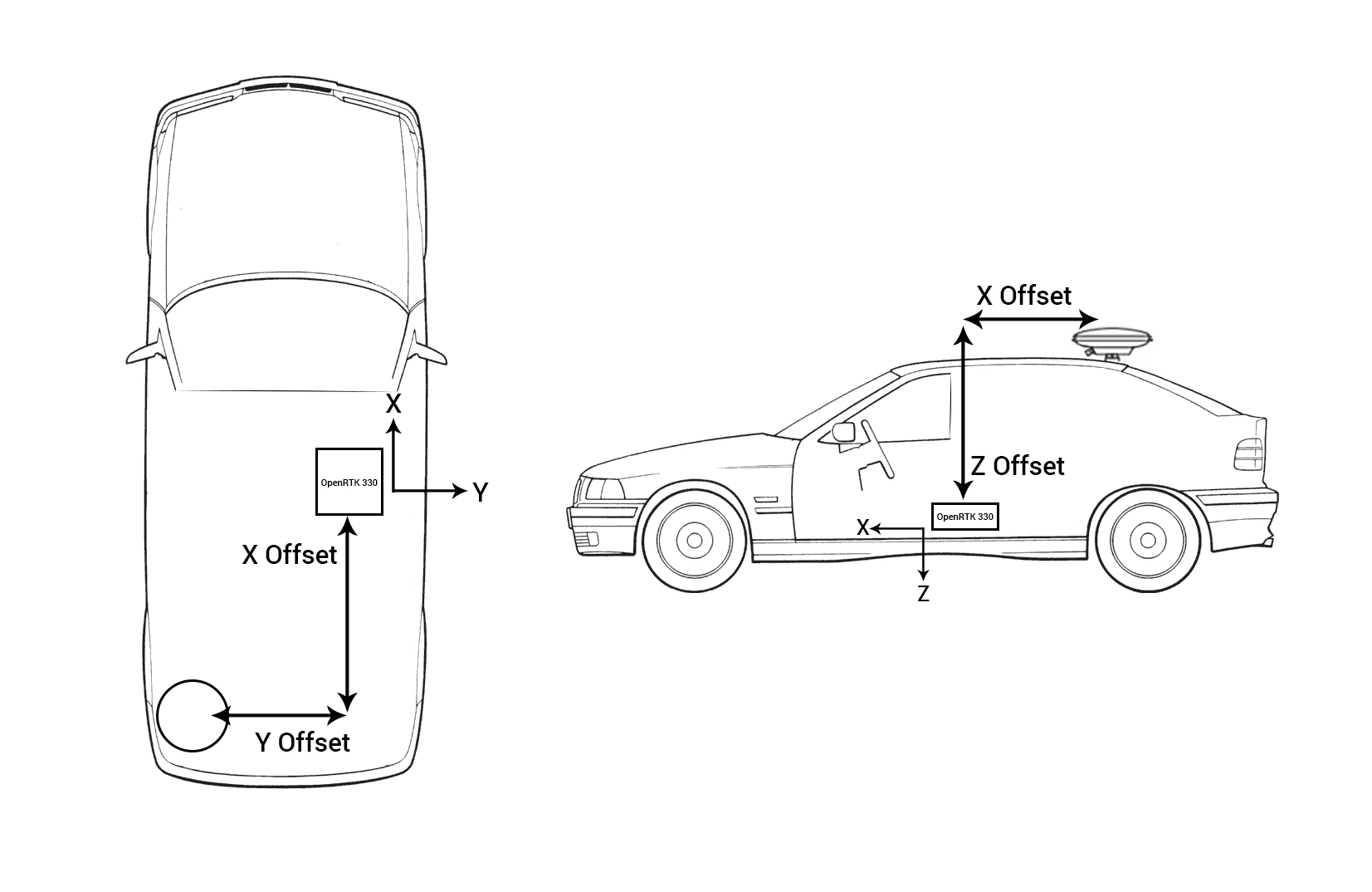
- GNSS antenna lever-arm: GNSS position is estimated to the phase center of the GNSS antenna, and INS position is estimated to the center of the navigation of the IMU. The translation from the IMU center to the phase center of the GNSS antenna has to be known and applied to the integrated system via user configuration of the antenna lever-arm. The GNSS/INS integrated solution outputs position at the IMU center. For example, the lever arm in the figure below is [x, y, z] = [-1.0, -1.0, -1.0] meter.
- User output lever-arm: If user wants the above GNSS/INS integrated solution output at a more useful position, the translation between the IMU center and the designated point of interest has to be known and applied via user configuration of point of interest lever-arm.
Rotation offset: If the axes of the IMU body frame of the installed OpenRTK330 unit is not aligned with the vehicle frame, the orientation of the IMU relative to the vehicle also has to be known and applied via user configuration of rotation angles between the IMU body frame and vehicle frame. For example, given a installation setup as shown by the following figure
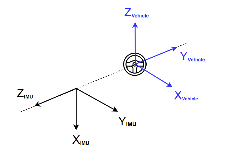
We have to mathematically rotate the IMU body frame to align with the vehicle frame, in the following order:
- Rotate IMU cooridnate frame to get z-axis aligned
- Rotate IMU cooridnate frame to get x-axis aligned
- Rotate IMU cooridnate frame to get y-axis aligned
For the example above, firstly rotate 90 degrees clockwise along IMU y-axis to align z-axis of two frames,
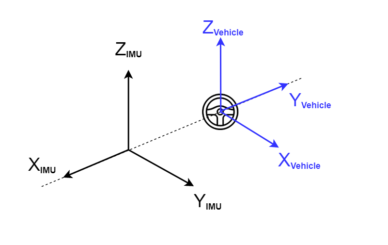
Then rotate 90 degrees counter-clockwise along IMU z-axis to align x-axis of two frames.
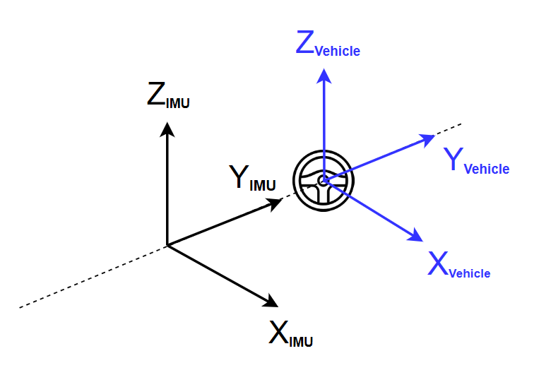
The final rotation matrix angles that user has to configure are [x, y, z] = [0, -90, 90] degrees.
Odometer Input from Vehicle
To fully explore the dead reckoning (DR) for vehicular positioning, OpenRTK330LI EVK has the following three options to get the Odometer data input from the vehicle:
- CAN interface
- wheel-tick signal and FWD (i.e. forward) signal
- USER UART input message
CAN interface
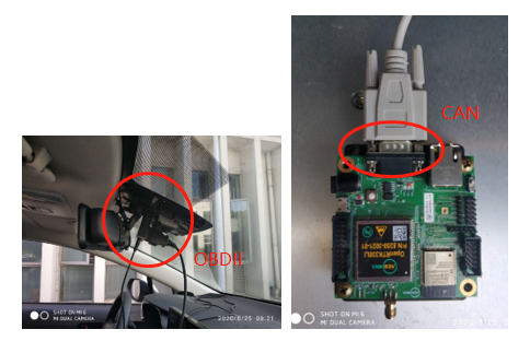
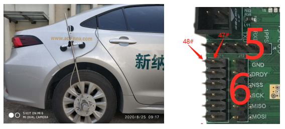
User is recommended to use a OBDII-CAN cable to connect the EVB DB-9 interface with one OBDII interface on the vehicle, the following photos show an example
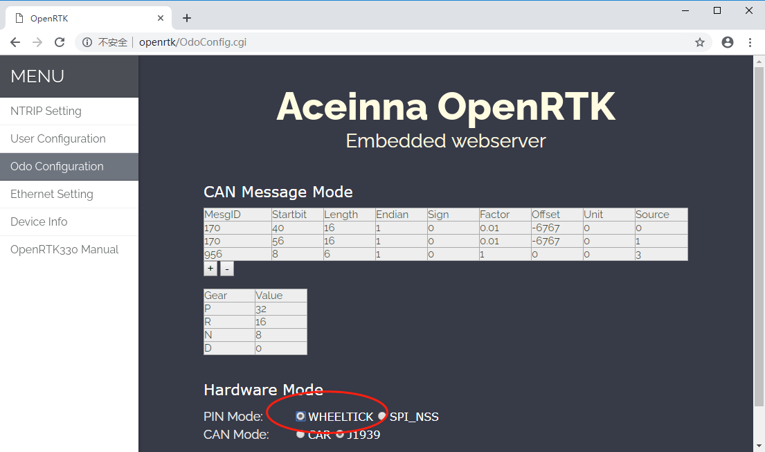
The CAN message contains vehicle Odometer speed data is different among manufacturers, OpenRTK330LI EVK provides user configuration on the internal Web interface (https://openrtk) to accommondate the different input CAN messages, as shown below
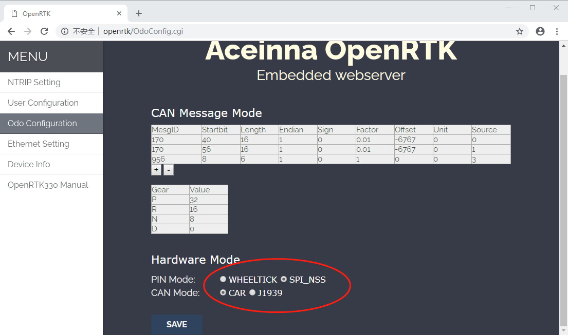
User has to check the “CAR” option for the CAN mode to enable the data input working mode of the CAN interface, as shown in the red circle. In the table above, user input the following fields to configure how the OpenRTK330LI module should parse the incoming Odometer message from CAN bus:
- MesgID: CAN message ID, decimal value
- Startbit: the number of starting bit of the Odometer data
- Length: the Odometer data Length in number of bits
- Endian: 0 - little endian; 1 - big endian
- Sign: 0 - unsigned; 1 - signed
- Factor and Offset: actual Odometer value = (original value + Offset) * Factor
- Unit: 0 - km/h; 1 - mph; 2 - m/s
- Source:
- 0 - right-rear wheel speed (RR)
- 1 - left-rear wheel speed (LR)
- 2 - vehicle speed (combined)
- 3 - gears: fill-in the gear (P, R, N, and D) value in the table below
There are two options to input the vehicle speed depending on the Odometer CAN messages,
- Configure the source to have RR and LR enalbed to obtain aveaged real wheel speed
- Configure the source to have a single combined vehicle speed
and the first option above is recommendded.
USER UART interface
With this approach, user need to extract vehicle speed information from the CAN bus or the wheel speed encoder and send in the real vehicle speed value through the USER UART, using the “cA” packet described in the USER UART data protocol section.
Wheel-tick encoder interface
Another approach to integrate vehicle speed for DR is shown below. A typical aftermarket wheel-tick encoder is shown on the left. Note that OpenRTK330LI EVB currently only supports one wheel-tick encoder input. As shown by the right side photo below, the phase-A and phase-B should connect with the #47 and #48 jumper on the EVB, respectivelly. The input voltage for the pins of OpenRTK330LI EVB is 3.3 v, if the wheel-tick encoder output voltage does not fit, user has to bring in additional voltage conversion circuits or module.
In the current design, the wheel-tick input processing takes over the interrupter of the MCU from the SPI communication ports, thus user needs to choose one of two working mode on the internal web interface page, as shown by the red circle in the figure below