With a PC
Using the OpenRTK330L EVK to evaluate the OpenRTK330L product with a PC requires
- access to the online web based Aceinna Navigation Studio (ANS) via the Micro-USB connection between the EVB and the PC
- access to NTRIP server over the internet via a Ethernet connection between the EVB and the PC
Usage
- Power and data link
Connect the EVB with a PC using a Micro-USB cable, and the YELLOW LED (#12 on the EVB figure above) flashes. The EVB is powered on, and four serial ports are established on the PC.
- Antenna
Connect a GNSS multi-frequency antenna to the SMA interface (#2 on the EVB figure), the GREEN LED (#12 on the EVB figure above) flashes if the incoming GNSS signal is valid
- Network
There are two ways of for the OpenRTK330LI EVB gets access to internet:
Use an Ethernet calbe to connect the EVB with a network router or switch, and then connect a PC to the same router/switch using an Ethernet cable. The OpenRTK330LI EVB gets internet access and assigned an IP address in the local network via DHCP.
The other way is using an Ethernet cable to connect the EVB and the PC directly, which requires internet sharing between the PC and the EVB. For example, with a Windows 10 PC,
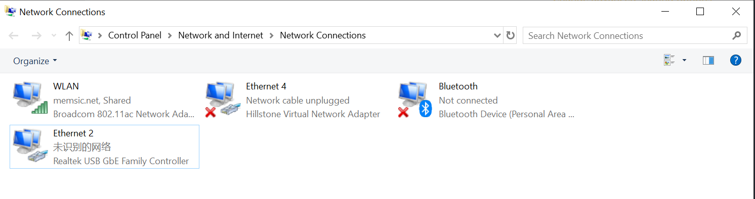
Go to Control PanelNetwork and InternetNetwork Connections, an Ethernet subnetwork is established for the Ethernet connection between the EVB and the PC, e.g. “Ethernet 2” as shown below.
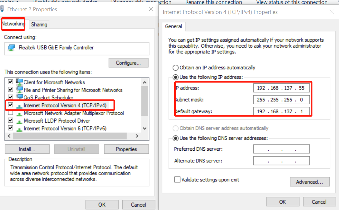
Right-click “Ethernet 2”, and then click “Properties”, on the “Networking” tab, click “Internet Protocol Version 4 (TCP/IPv4)”, configure the IP settings as follows: the gateway has to be 192.168.137.1, and the subnet mask has to be 255.255.255.0, while the IP address can be assigned to one that has not been taken in the network 192.168.137.xx.
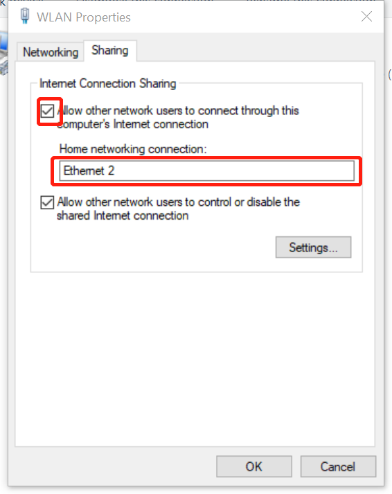
Then, right-click WLAN (assuming the PC uses WiFi for internet access), go to Properties->Sharing, check the “Allow other network users to connect through this computer’s internet connection”, and select “Ethernet 2” on the drop down menu below, click “OK” to enable the EVB to have access to internet shared by the PC.
- Device Configuration on the Embedded Web Pages
A lightweight TCP/IP web service is embedded inside the OpenRTK330 firmware, user can access the device configurations on the embedded web pages when the device and the PC are in the same local Ethernet network (connected to the same router or direclty connected). Open a browser (Google Chrome is recommended), visit http://openrtk,
You will firstly see the following device running status page
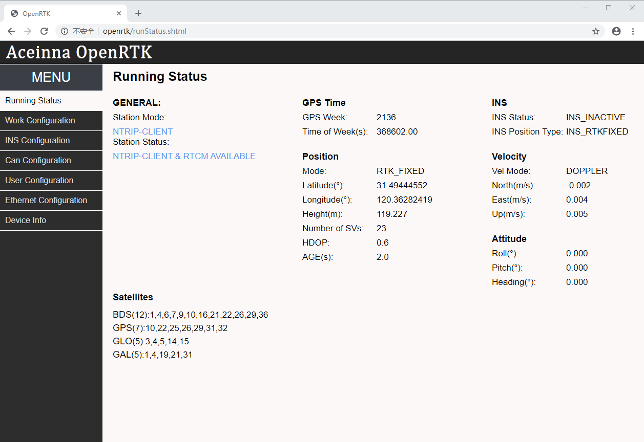
Besides the positioning information, this web page displays the working mode and status of the device on the most left-upper conner,
Station Mode, has the following two values:
- NTRIP-CLIENT: the device works as a NTRIP client (Rover), and is used as a positioning/navigation equipment
- NTRIP-SERVER: the device works as a NTRIP server (Base), and broadcasts its GNSS data to NTRIP clients for differential GNSS operation
and the mode changes when the user configures the device differently in the “Work Configuration” tab.
Station Status, has the following thirteen values:
- “Waiting…”: waiting for changes to take effective
- “NTRIP-CLIENT & CONNECT…”: trying to connect with a NTRIP server
- “NTRIP-CLIENT & CONNECT FAIL”: failed to connect with a NTRIP server
- “NTRIP-CLIENT & CONNECTED”: connect with a NTRIP server successfully, waiting for GNSS correction data
- “NTRIP-CLIENT & RTCM AVAILABLE”: received GNSS correction data successfully from the NTRIP server
- “NTRIP-SERVER & CONNECT…”: trying to connect with a NTRIP caster
- “NTRIP-SERVER & CONNECT FAIL”: failed to connect with a NTRIP caster
- “NTRIP-SERVER & CONNECTED”: connect with a NTRIP caster successfully, waiting to output GNSS correction data
- “NTRIP-SERVER & RTCM OUTPUT”: outputting GNSS correction data
- “OpenARC CONNECT…”: trying to connect with Aceinna’s OpenARC cloud service (e.g. NTRIP server and data service)
- “OpenARC CONNECT FAIL”: failed to connect with Aceinna’s OpenARC cloud service
- “OpenARC CONNECTED”: connect with a Aceinna’s OpenARC cloud service successfully, waiting for GNSS correction data
- “OpenARC RTCM AVAILABLE”: received GNSS correction data successfully from Aceinna’s OpenARC cloud service
On the left side menu bar, click “Work Configuration” tab to choose the following working mode of the device and configure it accordingly:
Rover: works as a nomarl GNSS positioning device that is also referring to “NTRIP client”, and receives GNSS data correction from a NTRIP server that has to be configured with the following information, as shown by the “OpenARC Client” tab below
- IP: openarc.aceinna.com
- PORT: 8011
- Mount Point: RTK
- User Name: username
- Password: password
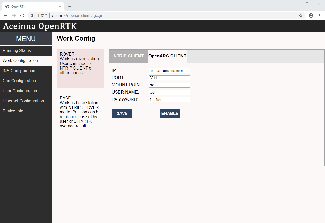
OpenARC is a cloud service provided by Aceinna for users in the United States to receive nation-wide GNSS correction data for RTK operation, without the need to set up a local GNSS base station. More details refer to the section “OpenARC Service” (click here) in this tutorial.
Base: works as a GNSS reference station with known position and sending GNSS data to “NTRIP server” to be used as GNSS data correction
- Live Web GUI on the Online ANS Website
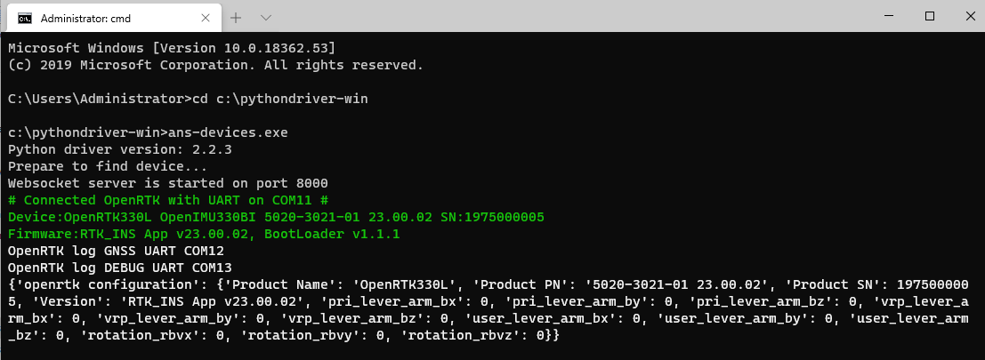
Download (click here) the latest Python driver executable (v2.2.4 and later), and run it in a command line, for example:
cd c:\pythondriver-win
.\ans-devices.exe
Check the console output, the Python driver connects the device and the online ANS website, if successfully, the following connection information is displayed
Go to the online ANS, on the left side menu bar, click “Devices”->”OpenRTK”, then we will have the “OpenRTK Monitor” webpage as shown below, and the center “Play” button is highlighted indicating correct device connection with the Web GUI,
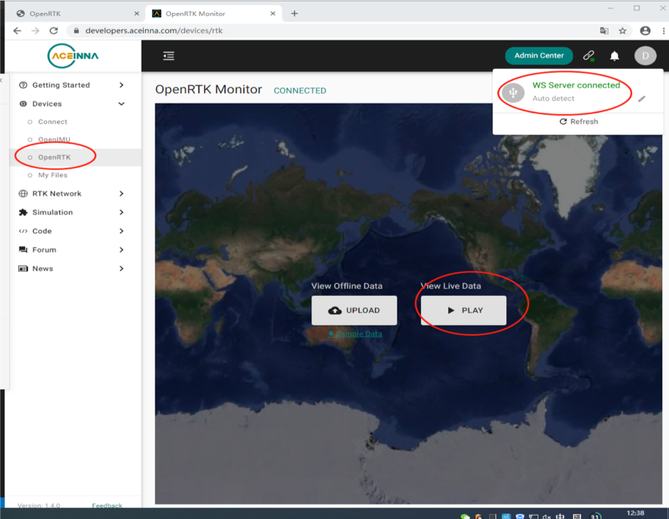
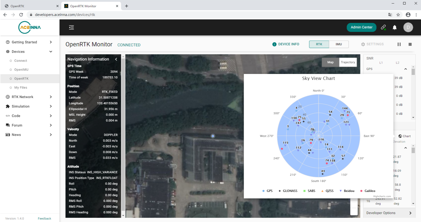
Click “Play”, you will have a live web GUI showing positioning information, map presentation and associated satellites information
- Data Logging and Parsing on a PC
With the UART/Serial port
When the device is connected with the PC via the micro-USB cable, the running Python driver is logging all serial port output into files, including raw GNSS/IMU data, positioning solution and the device configuration. These files are located in a subfolder labelled “.pythondriver-windataopenrtk_log_xxxxxxxx_xxxxxx”, e.g.
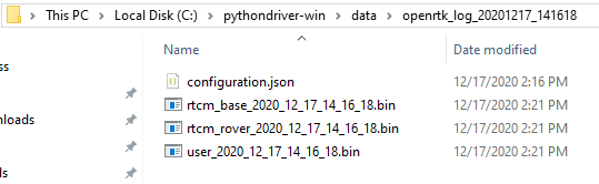
which,
- configuration.json: is the device configuration information
- rtcm_base_xxxx_xx_xx_xx_xx_xx.bin: is the received GNSS RTK correction data through internet, in RTCM format
- rtcm_rover_xxxx_xx_xx_xx_xx_xx.bin: is the GNSS raw data from the device, in RTCM format
- user_xxxx_xx_xx_xx_xx_xx.bin: is the output from the USER UART, including NMEA0183 messages in ASCII format, raw IMU data and GNSS RTK/INS solution in binary format
Go to the “openrtk_data_parse” subfolder, run the parser executable as below
cd c:\pythondriver-win\
.\ans-devices.exe parse -t openrtk -p ..\data\openrtk_log_20201217_141618
A subfolder with the name “user_xxxx_xx_xx_xx_xx_xx_p” is created and contains the decoded files all in ASCII format, e.g.
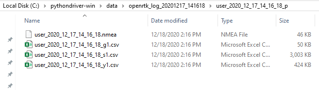
which:
- user_xxxx_xx_xx_xx_xx_xx.nmea: contains the GGA and RMC NMEA0183 messages
- user_xxxx_xx_xx_xx_xx_xx_g1.csv: is the GNSS RTK solution
- user_xxxx_xx_xx_xx_xx_xx_s1.csv: is the raw IMU data
- user_xxxx_xx_xx_xx_xx_xx_y1.csv: is the GNSS satellites information that are used in the solution
With the CAN Interface
User could use a CAN-USB (e.g. https://canable.io/) or CAN-TTL adapter to connect with the DB-9 male interface on the EVB to log and parse the CAN messages (click here for definitions). Note that user has to write their own CAN message parsing code using the provided lib or open-source code from the adapter provider.